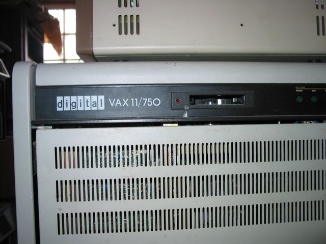
The second implementation of the VAX instruction set, codenamed COMET. Unlike the VAX-11/780 this one, can run from single phase power, was built of custom TTL gate arrays instead of Schottky TTL chips. This article give a brief description of the various gate arrays used. The cycle time of the CPU was 320 ns vs 200 ns for the 11/780. The performance was approximately 60% of the 11/780 but the size was down to one third. Documentation To start with I compiled list of and downloaded all possible documentations available on internet related to the VAX-11/750. Below is a list of all Field Maintenance Print Sets, Technical Documents, Installation guides, technical manuals that I could find. Technical Descriptions
Installation and Acceptance manual
Field Maintenance Print Sets
Technical manuals
Others Our VAX-11/750 Well. We have actually three VAX-11/750 in varying condition. The previous owner is two different computer clubs that simply lost interest in them. Prior to that one of them have been in use by Huddinge Sjukhus and the other at Ericsson. The idea is to put together one running machine and have spares to make it run for many years. One item that is missing for all of them is the front plate covering the card cage and also is a lock for the front door. Anyone have that one? Part number 7020272-00. Power supplies Since we have three different machines and in total four sets of power supplies the starter is to verify the correct operation of a complete power supply set. Each set consists of a 2.5 V / 85A supply, a 5V / 135 A supply and a power controller. The general idea is to check out the best looking pair by reforming the big smoothing capacitors on the inlet and then run them at nominal voltage with a dummy load. This is the  big 2.5V 85A H7104C power supply. These supplies are very heavily built and looks like they can last forever. The 200 VDC 4500 uF inlet smoothing capacitors has already been removed for reforming using a variac, a rectifier and a 220 kOhm resistor. Please  While looking at the various boards in the 5V supply one board has been subjected to some kind of corrosion, possibly due to a leaking capacitor. The nearby electrolytic capacitors on this board is to be replaced as a pre-caution. 5V supply squealing With all capacitors reformed and reinstalled I constructed proper dummy loads. The connectors that is used all over the place in this power supply was originally made by Amphenol but now it is Tyco Electronics and is called Universal Mate-N-Lok. For example the housing for the 15 pin line input is part number 1-480710-0. The crimp pins are 350218-1. But the crimp tool is extremely expensive. I use a plier and then solder them to get good contact. When switched on it was just a high pitched loud squealing noise from the power supply and no output at all. In the H7104D supply there are two separate AC inputs. One that is through a small transformer that produces a +11 V and a 5V reference to bootstrap the supply and then the full AC line which is rectified and applied to the two big capacitors. By running only the former from line voltage and applying power to the latter from a variac and a protection transformer I could work with the supply without risking my health. One peculiarity with the H7104 is that it won't start switching unless the rectified AC line is above 200 VDC. There is a circuit that monitors this and disables some portion of the switching drivers. By simply short circuit Q9 collector to ground this circuit is disabled and the supply believe everything is OK. Then to verify the main switch I removed the output transformer and inserted a 220 ohm resistor in its place. Now I studied the waveforms on all main switch transistors and one half looked very strange. No switching at all. When I desoldered these and measured them one of them turned out to be a short circuit. A 2N6547 has to be purchased. To be able to continue to work with the supply I borrowed one transistor from the 2.5V supply and continued by reinserting the main transformer into the loop. The loud squealing was gone but now it consumed considerable mount of power unloaded. It took 10 amps at 25 V input. Certainly not normal. The decision was to decouple the output rectifier stage to verify the output stages separately. While doing so I recognized that one of the output rectifier was short circuited. Four new old stock Unitrode USD5096F 35V / 35A diodes has been ordered. 5V supply running again! I borrowed an Unitrode Schottky diode from a another spare power supply and fitted it into the failing supply. Starting by running it off the variac was successful. With circa 80V input it delivered 3V output in a 0.5 ohm load. Now it was time to put the entire power supply back together and test it connected to the grid. And indeed it was running. I ran it for a couple of minutes into the dummy loads which soon had temperatures around 80 degres centigrade and the voltage was stable at 5.18V. I think this is fine for now and I will focus on the 2.5V supply instead. Broken diodes again Before even trying start the 2.5V supply I checked the output power diodes and the power switching transistors. All the switch transistors were OK but two more short circuited diodes were noted. What is it with these diodes? I have been unable to find the data sheet but they are noted as 35A 35V Schottky diodes. In the 5V supply which uses four diodes the max current is very close to the simultaneous max of all four together. But in the 2.5V supply the maximum current is 85A. A much better margin even though it is only using three diodes. It is indeed strange that the parts list in the schematic list these diodes as "60 AMP POWER SCHOTTKY DIODE". The part number is 1114197-00 and is used in for example the power supply of the PDP-11/44 as well. Is the diode used not up to what is specified or do I have the wrong specifications? It has been impossible to find the data sheet for the Unitrode USD5096F diode. Testing the 2.5V supply The 2.5V supply is a little bit different than the 5V supply in that it does not have the +11V bootstrap supply as in the 5V supply. The output windings of the small transformer on the motherboard is not connected to anything at all! On the other hand this supply relies on the 5V supply delivering +12V, -12V and +5V. It also has a clock input to synchronize the switchers in both the 5V supply and 2.5V supply. Thus the procedure to test this supply standalone is a bit different in that we need to supply +12V to J1:13,14, -12V to J1:5,6, +5V to J1:15,16 and ground to J1:3,4 from an ordinary PC power supply. Then as in the case with the 5V supply we connect the variac to input terminals 4 and 5. To simulate that the RAW DC SENSE signal is asserted we simply connect the Q3 collector to ground. Then the PSU starts switching and with around 100 VDC over the input filter caps it delivers 1.45 V out in the 0.25 ohm load. So it just seams that this supply now is OK. Load testing With both supplies hooked up together and all dummy loads connected I plugged them into the wall outlet and ran them for approximately five minutes until it started smelling from the dummy loads. All voltages were very near the specified and ripple on the main voltages were in the limits. I now consider the power supplies OK. Note that the picture below is taken with marginal check set to HI for the 5V supply to the right, thus the voltage is 5.23 V.  Serial Numbers Of the three machine we have one is missing the serial number sticker on the back. The other two has two leading letters, GA, which indicate that is is assembled in the Galway plant.   So the first one, GA05613 seems to be a bit older than the second one, GA07336. And then we know nothing about the last one. Boards The VAX-11/750 contain several boards that make up the CPU.  This is the Floating Point Accelerator. It has a many gate array chips and then also 7 8x8 multiplier chips a number of 74S381 ALU chips. It has its own 512x80 bits of microcode. This module goes into slot 1.  This is the L0002 DPM - Data Path Module. This is here were the arithmetic logic, rotator logic, main registers and the micro sequencer. This module goes into slot 2.  This is the L0003 MIC -Memory Interconnect Module - It contain the address logic, translation buffers, cache memory and data routing and alignment logic. This module goes into slot 3.  This is the L0004 UBI - Unibus Interface. Connects to the TU58 console media. has the console serial port. Interfaces the Unibus. This module goes into slot 4. One of the UBI modules have problems to communicate with the TU58 (emulator). The Emulator is receiving garbage all the time. This could be a problem with a gate array. But more likely is that the 1488 transmitter chip is damaged. E111 is going to be replaced to see if that fixes the problem.  This is the L0008-YA - PCS module. Patchable Control Store. It is an upgrade to the L0005 board. This module contain the 6k x 80 bit control store in bipolar PROMs. But also 1k x 80 patch control store. The ROM based control store can be patched with the contents of the RAM if a flag RAM is set. This module goes into slot 5. This board also has the main clock generator. A 18.75 MHz clock generator which is divided by 3 to produce a 160 ns clock and then further to a 320 ns clock used by the micro sequencer. All clock division takes place on the DPM (L0002) module so the PCS module only contains the clock oscillator itself. Since one of the L0008 board is malfunctioning giving a red light directly and the DPM diagnostics says "M CLOCK HUNG" my theory is that the crystal oscillator is bad on that particular board, but replacing the oscillator didn't cure the board so there has to be more to it.  This is L0006 - RDM. The remote diagnostic module. It is a property of Digital Equipment - I hope they don't want it back. It contain a 8085 microprocessor by which is possible to do very low level diagnosing of the machine locally or remotely. This module goes into slot 6. This is dumps of the four 2kbyte ROMs on the board: 23-216E2, 23-217E2, 23-218E2 and 23-219E2. Since one of the boards fails with a ERR: RAM:94 message I liked to understand what memory chip that caused the problem. What is the source of the number 94? The four ROMs was concatenated into one file and disassembled. At startup the system does all sorts of checking. First a simple memory check, then a ROM checksum test and then a more extensive memory check which tests the memory with several different patterns. ROM is between 0000h and 1FFFh. RAM memory starts at 8000h and extends to B7FFh. 94 indicate the high byte of the address that is failing. The tricky question is which chip is that. To my knowledge there are no schematic for this board. One pair out of 14 paris of 2114 memory chips is the culprit, so there has to be 14 chip select signals generated by some circuitry on the board. Addresses A13 through A10 has to go into this selector. A 74154 or a couple of 74138 would do the job. Indeed there are a 74154 on the board but is too far away from the memory system. The two 74LS138 on the row below the 8085 processor (E140 and E142) is more likely. Beeping the board shows that these are indeed connected to the memory array. E142 is connected to the topmost 8 pairs of 2114 chips. E140 is connected to the lower 6 pairs of 2114 chips. Output 0 is connected to the pairs to the left. This means that address 8000-83FF is in the top left most chips, 8400-87FF is the chips next and the onwards. Failure code 94 then indicate failure of the pair E203 and E184. Replacing these two memory chips made the RDM module work just fine!  This is the L0007 - MBA or Mussbus Adapter. It interfaces with various massbus disks or tape drives, like RM80 or TU78. This board goes into one of the CMI slots, 7 to 9. In these slots other CMI peripherals can be used, L0010 - DW750 a secondary unibus adapter or the CI750 for cluster interconnect.  This is the L0011 - Memory controller for memory boards with 16k chips, M8728. This board goes into slot 10 of the processor backplane.  This is L0022 - Memory controller for memory boards with 256 kbit chips (M7199). It also is able to handle boards with 64 kbit memory chips. By using two M7199 boards and six M8750 board you can reach the physical maximum of 14 Mbyte that is possible to address in the VAX-11/750. Power on With all power supplies in place the time had come to try to run the machine. The boards present in the machine were checked for correct position and the power was applied. There were just a line of hex digits and a >>> prompt and a line of hex digits. No %% indicating that it had passed the built in microcoded selftest, microverify. Since we have three of more complete board sets some boar swapping took place which gave all sorts of faults: Bright red on the error LED, Running directly after RUN and no console output, %C micro verify failure and also %O microverify error. Not very promising. The description for %C microverify indicated that the DPM wasn't working correctly. While %O described what looked like a MIC module failure. So I concluded when I had the %O failure coming on the console I started to change the MIC module until I found one that made it pass the microverify step and present a %% on the console. Running diagnostics So now lets see if everything was working. Lets us run the diagnostics. I attached a TU58 emulator to the console tape port to emulate the real thing. The actual TU58 wasn't in best shape and I didn't have all TU58 cassettes readily available. At first I was mistaken about the baud rate but when I set it to 19200 it was possible to load and run the RDM based micro diagnostics. In this case the RDM module loads different test sequences that exercises the internals of the DPM and MIC module. As it seems all tests of the MIC and DPM passed successfully. Oe question that remain is why the L0022 mamory controller board is detected as a L0016. Either it is because there were only 1 Mbyte boards installed or the diagnostic is buggy. Booting diagnostics directly With DPM and MIC in good shape the next step was to boot some diagnostics directly from the >>> prompt. First the Hardcode VAX-11 Instruction set test that is a bootable TU58 tape. Failing TB/Cache test When trying to run the TB/Cache test it fails on me for some reason. Maybe there is a real fault, although the microverify which includes some simple tests of the Translation Buffer (TB) and Cache. Or the version of the diagnostic is not compatible. Unfortunately the diagnostic is not printing its version. When executing this diagnostic later it passed. Exactly why it failed earlier and passes now is not known. Perhaps cleaning all gate arrays also fixed this problem. At least we know that this test shall pass. Booting the console tape The Console tape includes the BOOT58 program to boot other devices and also run diagnostics and load other programs into memory. The good thing is that this program ran successfully! So when the machine runs code the RUN light is green and the ERROR light glows - all is normal. When there is an error the ERROR light is shining annoyingly bright. Below everything is running as it should!  Cleaning gate array sockets The RDM diagnostics is very good for investigating problems in the cards. I inserted a DPM (L0002) which I knew was problematic since it didn't pass micro verify and the ran the diagnostics. It indicated a problem with gate arrays DC621 and DC617. By simply removing the gate arrays from their sockets and cleaning both the chip and the socket carefully the board passed the diagnostic. Bad contact in the sockets is very common and cleaning all sockets solved several boards. Booting Ultrix and VMS When all diagnostics passed I tried to boot both VMS 6.1 and Ultrix-32 4.0. Both got stuck during the startup phase. Ultrix-32 was stuck when initializing the unibus. By re-installing the MASSBUS adapter L0007 (there had been one in the system once) and removing uncessary card on the Unibus I finally got the machine to boot. Instead of a real disk I used a small CD card attached to a SCSI2SD adapter and then to a Emulex UC17 unibus SCSI board that emulates MSCP. Below booting Ultrix-32 4.0: And then VMS: While cleaning the gate arrays of the board I discovered that the contact material of some gate arrays were coming of when cleaning. Looking carefully, there were small spots of green and the gold plating was bulging a tiny bit. Just scratching a little bit and the gold plating fell off.  Unfortunately there are probably no way to repair this. We are very interested in spare gate arrays to keep the machine running. Those we are especially interested in are: DC608D, DC609E, DC614C, DC615D, DC616C, DC622B, DC624E, DC625B, DC626B and DC627B. if you happen to have any of those, please get in contact! Card inventory This is the total inventory of CPU cards for the VAX-11/750 we have:
Links Here are a few links to valuable information. |
Computers > Digital Equipment >